Foundations
Axial Pile Capacity Calculator
Combine project-specific average shaft and toe resistances to estimate ultimate and allowable compression capacity for one circular pile.
Engineering schematic
Single-pile axial resistance
Static symbolic figure. Enter project values in the calculator fields below.
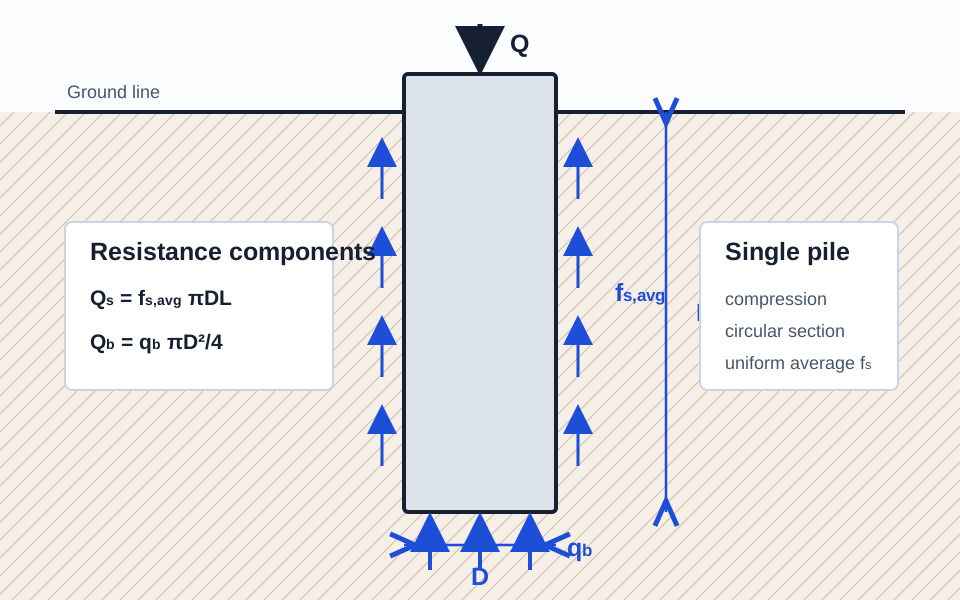
- D, L
- pile diameter and embedded length
- fs,avg
- project-specific average unit shaft resistance
- qb
- project-specific unit toe resistance
- Qs, Qb
- ultimate shaft and toe resistance components
Result
Allowable axial geotechnical capacity: 893.47 kN
Pile perimeter
1.885 m
Shaft surface area
33.93 m²
Toe area
0.283 m²
Ultimate shaft resistance
1526.81 kN
Ultimate toe resistance
706.86 kN
Ultimate axial capacity
2233.67 kN
Allowable axial capacity
893.47 kN
Step-by-step calculation
- Pile resistance areas
- Shaft and toe resistance
- Ultimate capacity
- Allowable capacity
What this means
The result combines the entered average shaft and toe resistances for one circular pile. Confirm settlement, structural capacity, downdrag, lateral behavior, group effects, and load-test requirements separately.
Important limitations
- Unit shaft and toe resistances must come from a project-specific geotechnical method or recommendation; this calculator does not derive them from soil descriptions.
Assumptions
- Single vertical circular pile
- Uniform average unit shaft resistance over the embedded length
- Toe resistance acts over the full gross base area
- Compression loading without scour or downdrag
Formula Used
Step-by-Step Example
A 0.6 m diameter pile embedded 18 m with average shaft resistance 45 kPa and toe resistance 2,500 kPa has approximately 2,234 kN ultimate and 894 kN allowable capacity at FS = 2.5.
Engineering Notes
- Derive unit shaft and toe resistances from a project-specific static method, in-situ testing correlation, load testing, or geotechnical recommendation.
- Layered profiles should normally be summed by layer rather than represented by one unweighted average shaft resistance.
- Check settlement or load-transfer response; geotechnical serviceability may control before the calculated allowable capacity is reached.
- Evaluate pile structural capacity, group efficiency, block failure, downdrag, uplift, lateral response, scour, constructability, and load-test criteria separately.
FAQ
Does this calculator determine unit shaft and toe resistance?
No. Those inputs must come from an appropriate project-specific geotechnical method or recommendation.
Can I model layered soil?
Use a separate shaft area and unit resistance for each layer, sum those contributions, and then add toe resistance. This initial tool accepts one average shaft value.
Is allowable capacity the same as design capacity?
Not necessarily. The required resistance factors, safety factors, load combinations, testing, and settlement criteria depend on the governing design framework and project requirements.